
Water supply issues are common in many regions, and often, the timing of water availability is unpredictable. You might have to wake up at odd hours just to switch on your motor pump and wait for the tank to fill up. To avoid these inconveniences, an Auto Water Pump Switcher offers a solution that automates this process. It switches the pump on when water is available and turns it off when the water supply stops. In this guide, we’ll explore how this system works, its components, and how to build one yourself.
Problems with Manual Water Pump Systems
For many people, managing water supply can be a tedious task. Water supply timings can vary significantly, and often people have to wake up early or stay alert throughout the day to manually turn on their water pumps. This process is not only inconvenient but also time-consuming. Additionally, there is the risk of overfilling the tank if the pump is left on for too long, leading to water wastage.
What is an Auto Water Pump Switcher?
An Auto Water Pump Switcher is an electronic device designed to automate the process of switching your water pump on and off based on water availability. The system detects when water is being supplied and automatically powers on the motor to pump water into your tank. When the water supply stops, the pump is automatically turned off. This eliminates the need for constant monitoring and manual intervention.
How the Auto Water Pump Switcher Works
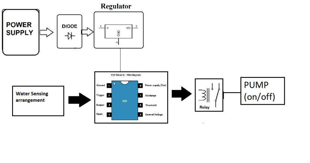
At the heart of this project is the 555 Timer IC, which works as a controller that receives input from the water-level sensor. When water is detected by the sensor, the circuit sends a signal to the relay, which in turn powers on the water pump. Once the sensor detects that the water has stopped flowing, it sends another signal to turn off the pump. This ensures that the pump operates only when needed.
Core Components of the Project
To build this auto switcher, you’ll need the following components:
- 555 Timer IC: Acts as the control unit for the entire system.
- Resistors and Capacitors: These regulate the timing and ensure stable operation of the circuit.
- Cables & Connectors: To connect the different components.
- Diodes: To prevent reverse current flow, protecting the circuit.
- PCB (Printed Circuit Board): A base to assemble and solder all components.
- LEDs: To provide visual indications of the pump’s status.
- Switch: Allows manual override in case of any issues.
- Relay: Acts as a switch to control the pump’s power.
Detailed Circuit Explanation
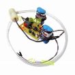
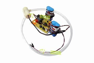
The project works based on a simple circuit involving the 555 Timer IC and a relay. The 555 Timer IC is configured in such a way that it reads the input from the water sensor. When water is detected, it triggers the relay to turn on the pump. The relay, being an electromechanical switch, handles the high voltage required by the motor.
Working Principle
The system primarily operates on a water-level sensing mechanism. The sensor is placed in a location where it can detect the incoming water supply. As soon as water is detected, the 555 Timer IC activates the relay, which then switches on the pump. When the sensor detects that the water flow has stopped, the relay cuts off the power, turning off the motor. This ensures that water is pumped only when required, conserving energy and preventing wastage.
Benefits of Using an Auto Water Pump Switcher
- Saves Time: No need to monitor the water supply constantly.
- Conserves Water: Prevents overflow and unnecessary water wastage.
- Extends Pump Life: Ensures that the pump operates only when needed, reducing wear and tear.
Practical Use Cases
This system can be used in:
- Residential Homes: Especially in areas with inconsistent water supply.
- Agricultural Fields: To automate the irrigation process.
- Commercial Buildings: To ensure that water storage systems are efficiently managed.
Step-by-Step Guide to Build the Auto Water Pump Switcher
- Step 1: Gather Components: Ensure you have all necessary parts like the 555 Timer IC, relay, sensors, etc.
- Step 2: Assemble the Circuit: Solder the components on the PCB as per the circuit diagram.
- Step 3: Connect the Relay: Attach the relay to the motor pump.
- Step 4: Test the Water Sensor: Ensure the sensor is working by simulating water flow.
- Step 5: Power the Circuit: Provide power and test the operation by observing the pump’s switching behavior.
Testing the Circuit
Once assembled, simulate water supply to test if the pump automatically turns on and off. If it doesn’t, check the sensor connections and ensure that the 555 Timer IC is functioning correctly.
Common Problems and Solutions
- Sensor Not Detecting Water: Check if the sensor is positioned correctly and if it’s receiving power.
- Relay Not Switching On: Ensure that the relay is properly connected to the motor and the IC.
- Pump Malfunction: Double-check all connections and confirm the relay is switching correctly.
Customization Options for Advanced Users
- Larger Pumps: Upgrade the relay and power supply to handle more powerful motors.
- Remote Control: Add Wi-Fi or Bluetooth modules to control the pump from a smartphone.
- Solar Power: Integrate solar panels to make the system energy efficient.
Safety Precautions
- Water and Electricity: Always ensure proper insulation and never handle electrical components with wet hands.
- Circuit Protection: Use diodes and fuses to prevent short circuits.